VSS
VSS的功能
VSS技術可以將兩台4500或6500變成一台邏輯的Switch,兩台共用設定檔
左邊為實際的網路架構,右邊是建立完VSS後,設備之間的關係
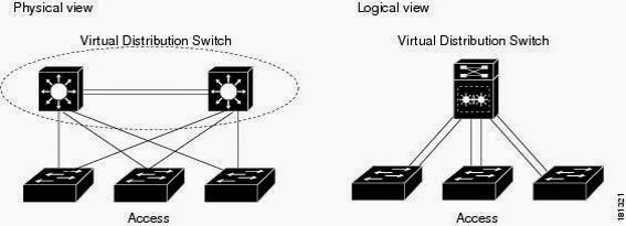 運用VSS技術可將兩台設備視為一台,減少L2收斂(STP)的時間和L3的節點數
好處
簡化設定的指令
更快的收斂速度
更少的網路資源
負載平衡
術語

Virtual Switching System (VSS)
將兩台實體switch視為一台虛擬的switch,再運用etherchannel技術兩台switch同時連接一台設備,達到L2/L3的備援機制和負載平衡
VSS Active Switch and VSS Standby Switch
當建立或重開VSS,兩台switch會協商他們的角色
一個會變為 VSS Active Switch,另一個為VSS Standby Switch
VSS Active Switch負責控制VSS的運作並提供管理VSS的介面 (例如,console interface)
VSS Standby Switch會將control traffic送到Active Switch,請Active Switch負責處理
VSS Active and Stnadby Swtiches都會處理封包轉送的動作
Virtual Switch Link (VSL)
為了要讓兩台switch視為一台switch,這兩台switch需要分享控制訊息(control information)和資料流(data traffic)
VSS硬體需求
VSS軟體需求
設定步驟
1. 驗證硬體/軟體是否支援VSS
2. 指定Virtual Switch Domain and Switch Numbers
2.1 兩台Switch都指定相同的Virtual Switch Domain number
2.2 設定一台為Switch1,另一台為Switch2
Virtual Switch Domain : 兩台Switch類似Cluster的方式綁在一起,此時需要一個容器收容這兩台Switch,這個容器就是Virtual Switch Domain。
Switch Numbers :雖然可以把兩台看成一台,實際上還是兩台設備,因此需要將設備編號,Switch才知道誰是誰。
先在SW1上面設定 Domain Number,再設定VSS內的Switch序號
兩台交換器的Domain Number必須一樣,而Switch 的序號必須不一樣
3. 設定VSL PortChannel
此時在實體介面上的PortChannel還沒有設定,也先不要設定。
兩台設備的VSL PortChannel Number要不一樣,如例子中的一個是5一個是10,只有VSL要這樣設定,這是為了當兩台合併後,可以分的出Active和standby
4. 將實體介面加入PortChannel
將實體介面加到Port-channel後所出現的警告訊息,在告訴我們原先gig1/1的設定會被清除,因為Port-channel已經被我們設定成switch virtual link。
另外,一旦下了 “channel-group” 指令,介面的狀態會變為 “notconnect”,介面狀態會是 Up/Down的狀況,直到重啟Switch
5. 將Switch轉換成 Virtual Switch mode
5.1 將Switch轉變為 Virtual Switch Mode
5.2 在提示訊息輸入 “YES”
(兩台Switch都要下這筆指令)
執行轉換Switch Mode的指令後,會自動重開機。
系統會自動將Running-config儲存到Startup-config內。
轉換完成後,介面的編號會變為 switch/module/port
一旦轉換完畢,就只能用Master的Switch操控,如果把Console接到Standby的設備上會看到如下字樣,且不能操作
6. 總指令
7. 驗證
show switch virtual
顯示兩台Switch的Domain、Switch Number、Role
show switch virtual role
顯示兩台交換器的詳細資料
sh switch virtual link
顯示Virtual Link的狀態
switch virtual link port-channel
顯示Virtual Link的Port-Channel的狀態
參考資料
Catalyst 4500 Series Switch Software Configuration Guide, Release IOS XE 3.4.0SG and IOS 15.1(2)SG
VSS技術可以將兩台4500或6500變成一台邏輯的Switch,兩台共用設定檔
左邊為實際的網路架構,右邊是建立完VSS後,設備之間的關係
好處
簡化設定的指令
更快的收斂速度
更少的網路資源
負載平衡
術語
- Virtual Switching System (VSS)
- VSS Active Switch and VSS Standby Switch
- Virtual Switch Link (VSL)
Virtual Switching System (VSS)
將兩台實體switch視為一台虛擬的switch,再運用etherchannel技術兩台switch同時連接一台設備,達到L2/L3的備援機制和負載平衡
VSS Active Switch and VSS Standby Switch
當建立或重開VSS,兩台switch會協商他們的角色
一個會變為 VSS Active Switch,另一個為VSS Standby Switch
VSS Active Switch負責控制VSS的運作並提供管理VSS的介面 (例如,console interface)
VSS Standby Switch會將control traffic送到Active Switch,請Active Switch負責處理
VSS Active and Stnadby Swtiches都會處理封包轉送的動作
Virtual Switch Link (VSL)
為了要讓兩台switch視為一台switch,這兩台switch需要分享控制訊息(control information)和資料流(data traffic)
VSS硬體需求
| Hardware | Count | Requirements |
| Chassis | 2 | Catalyst 4500-X系列交換器
支援Supervisor Engine 7-E和Supervisor Engine 7-LE的機箱。
Note
兩個機箱的Slots數必須相同,但+E和-E的機箱可以混合使用。
|
| Supervisor Engines | Supervisor Engine 7-E和Supervisor Engine 7-LE Catalyst 4500-X系列交換器 Supervisor Engines或System必須相同 |
|
| Linecard | WS-X4748-RJ45V+E WS-X4712-SFP+E WS-X4748-RJ45V+E WS-X4712-SFP+E WS-X4640-CSFP-E WS-X4748-UPOE+E WS-X4748-RJ45-E WS-X4606-X2-E WS-X4648-RJ45V-E WS-X4648-RJ45V+E WS-X4648-RJ45-E WS-X4624-SFP-E WS-X4612-SFP-E |
| iOS Version | Cisco IOS XE 3.4.0SG and ROMMON IOS Version 15.0(1r) SG7 |
| Minimum license | IP BASE or ENTSERVICES license |
設定步驟
- 驗證硬體/軟體是否支援VSS
- 指定Virtual Switch Domain and Switch Numbers
- 設定VSL PortChannel
- 將實體介面加入PortChannel
- 轉換Switch成Virtual Swith Mode
- 設定跨機箱的EtherChannel
1. 驗證硬體/軟體是否支援VSS
| SW1#sh ver | in IOS |
| Cisco IOS Software, IOS-XE Software, Catalyst 4500 L3 Switch Software (cat4500e-UNIVERSAL-M), Version 03.04.00.SG RELEASE SOFTWARE (fc3) |
| Cisco IOS-XE software, Copyright (c) 2005-2010, 2012 by cisco Systems, Inc. |
| All rights reserved. Certain components of Cisco IOS-XE software are |
| documentation or "License Notice" file accompanying the IOS-XE software, |
| or the applicable URL provided on the flyer accompanying the IOS-XE |
| SW1#sh ver | in ROM |
| ROM: 15.0(1r)SG7 |
| SW1#sh license image levels |
| Module name Image level Priority Configured Valid license |
| -------------------------------------------------------------------- |
| WS-X45-SUP7-E entservices 1 YES entservices |
| ipbase 2 NO ipbase |
| lanbase 3 NO lanbase |
| Module Name Role Current Level Reboot Level |
| -------------------------------------------------------------------- |
| WS-X45-SUP7-E Active entservices entservices |
2. 指定Virtual Switch Domain and Switch Numbers
2.1 兩台Switch都指定相同的Virtual Switch Domain number
2.2 設定一台為Switch1,另一台為Switch2
Virtual Switch Domain : 兩台Switch類似Cluster的方式綁在一起,此時需要一個容器收容這兩台Switch,這個容器就是Virtual Switch Domain。
Switch Numbers :雖然可以把兩台看成一台,實際上還是兩台設備,因此需要將設備編號,Switch才知道誰是誰。
先在SW1上面設定 Domain Number,再設定VSS內的Switch序號
兩台交換器的Domain Number必須一樣,而Switch 的序號必須不一樣
| SW1#conf t |
| Enter configuration commands, one per line. End with CNTL/Z. |
| SW1(config)#switch virtual domain 10 |
| Domain ID 10 config will take effect only |
| after the exec command 'switch convert mode virtual' is issued |
| SW1(config-vs-domain)#switch 1 |
| SW1(config-vs-domain)#exit |
| SW1(config)# |
| SW2#conf t |
| Enter configuration commands, one per line. End with CNTL/Z. |
| SW2(config)#switch virtual domain 10 |
| Domain ID 10 config will take effect only |
| after the exec command 'switch convert mode virtual' is issued |
| SW2(config-vs-domain)#switch 2 |
| SW2(config-vs-domain)#exit |
| SW2(config)# |
3. 設定VSL PortChannel
此時在實體介面上的PortChannel還沒有設定,也先不要設定。
兩台設備的VSL PortChannel Number要不一樣,如例子中的一個是5一個是10,只有VSL要這樣設定,這是為了當兩台合併後,可以分的出Active和standby
| SW1(config)#int port-channel 5 SW1(config-if)#switchport SW1(config-if)#switch virtual link 1 SW1(config-if)#no shut SW1(config-if)#exit *Jan 24 05:19:57.092: %SPANTREE-6-PORTDEL_ALL_VLANS: Port-channel5 deleted from all Vlans SW2(config)#int port-channel 10 SW2(config-if)#switchport SW2(config-if)#switch virtual link 2 SW2(config-if)#no shut SW2(config-if)#exit SW2(config)# *Jan 24 05:14:17.273: %SPANTREE-6-PORTDEL_ALL_VLANS: Port-channel10 deleted from all Vlans |
4. 將實體介面加入PortChannel
將實體介面加到Port-channel後所出現的警告訊息,在告訴我們原先gig1/1的設定會被清除,因為Port-channel已經被我們設定成switch virtual link。
另外,一旦下了 “channel-group” 指令,介面的狀態會變為 “notconnect”,介面狀態會是 Up/Down的狀況,直到重啟Switch
| SW1(config)#int range gig1/1 - 2 SW1(config-if-range)#switchport mode trunk SW1(config-if-range)# channel-group 5 mode on WARNING: Interface GigabitEthernet1/1 placed in restricted config mode. All extraneous configs removed! WARNING: Interface GigabitEthernet1/2 placed in restricted config mode. All extraneous configs removed! SW1(config-if-range)#exit SW2(config)#int range gig1/1 - 2 SW2(config-if-range)#switchport mode trunk SW2(config-if-range)#channel-group 10 mode on WARNING: Interface GigabitEthernet1/1 placed in restricted config mode. All extraneous configs removed! WARNING: Interface GigabitEthernet1/2 placed in restricted config mode. All extraneous configs removed! SW2(config-if-range)#exit |
5. 將Switch轉換成 Virtual Switch mode
5.1 將Switch轉變為 Virtual Switch Mode
5.2 在提示訊息輸入 “YES”
(兩台Switch都要下這筆指令)
執行轉換Switch Mode的指令後,會自動重開機。
系統會自動將Running-config儲存到Startup-config內。
轉換完成後,介面的編號會變為 switch/module/port
| SW1#switch convert mode virtual This command will convert all interface names to naming convention "interface-type switch-number/slot/port", save the running config to startup-config and reload the switch. Do you want to proceed? [yes/no]: yes Converting interface names Building configuration... Compressed configuration from 6551 bytes to 2893 bytes[OK] Saving converted configuration to bootflash: ... Destination filename [startup-config.converted_vs-20130124-062921]? Please stand by while rebooting the system... Restarting system. Rommon (G) Signature verification PASSED Rommon (P) Signature verification PASSED FPGA (P) Signature verification PASSED |
一旦轉換完畢,就只能用Master的Switch操控,如果把Console接到Standby的設備上會看到如下字樣,且不能操作
| SW2-standby> Standby console disabled |
6. 總指令
| 第一台Switch Conf t Switch virtual domain 1 Switch 1 exit Int po 5 switchport switch virtual link 1 Exit Int gi0/1 – 2 Switchport mode trunk Channel-group 5 mode on Exit Switch convert mode virtual |
第二台Switch Conf t Switch virtual domain 1 Switch 2 exit Int po 10 switchport switch virtual link 2 Exit Int gi0/1 – 2 Switchport mode trunk Channel-group 10 mode on Exit Switch convert mode virtual |
7. 驗證
show switch virtual
顯示兩台Switch的Domain、Switch Number、Role
| SW1#sh switch virtual Executing the command on VSS member switch role = VSS Active, id = 1 Switch mode : Virtual Switch Virtual switch domain number : 10 Local switch number : 1 Local switch operational role: Virtual Switch Active Peer switch number : 2 Peer switch operational role : Virtual Switch Standby Executing the command on VSS member switch role = VSS Standby, id = 2 Switch mode : Virtual Switch Virtual switch domain number : 10 Local switch number : 2 Local switch operational role: Virtual Switch Standby Peer switch number : 1 Peer switch operational role : Virtual Switch Active |
show switch virtual role
顯示兩台交換器的詳細資料
sh switch virtual link
顯示Virtual Link的狀態
switch virtual link port-channel
顯示Virtual Link的Port-Channel的狀態
參考資料
Catalyst 4500 Series Switch Software Configuration Guide, Release IOS XE 3.4.0SG and IOS 15.1(2)SG
留言
發佈留言